User guide
What is AeroFrame?
Computational aeroelastic analyses are often based on separate solvers for the aerodynamics and the structural analyses. In other words, aerodynamics may be analysed with a standalone CFD tool and the structural response is computed with a standalone FEM tool. To perform an aeroelastic analyses it is necessary to exchange data, namely loads computed by the CFD tool and deformations computed by the FEM tool.
AeroFrame is a framwork which facilitates the exchange of load and deformation data, and it coordinates the separate aerodynamics and structure solvers. AeroFrame performs “high-level” partitioned aeroelastic analyses and provides tools for load mapping and mesh deformations. The actual aerodynamics and structure solvers have to be plugged into the framework. This is done using small wrapper modules, one for the CFD tool and one for the FEM tool. In order to use AeroFrame it is only necessary to write two wrapper modules.
The following diagram illustrates the coupling, and a so-called aeroelastic loop which is solved to perform a static aeroelastic analysis. In this case, the CFD tool is PyTornado and the structure tool is FramAT (see also Related projects), though both tools are representatives of any arbitrary CFD or structure tool.

Fig. 2 Conceptual implementation of the aeroelastic loop to find static equilibria [Dett19]
The loop is illustrated below for an aircraft (OptiMale UAV [AgOp19]) in a pull-up manoeuvre. The analysis is described in more depth in [Dett19]. PyTornado and FramAT were used as CFD and structure solvers, respectively (see also Related projects).
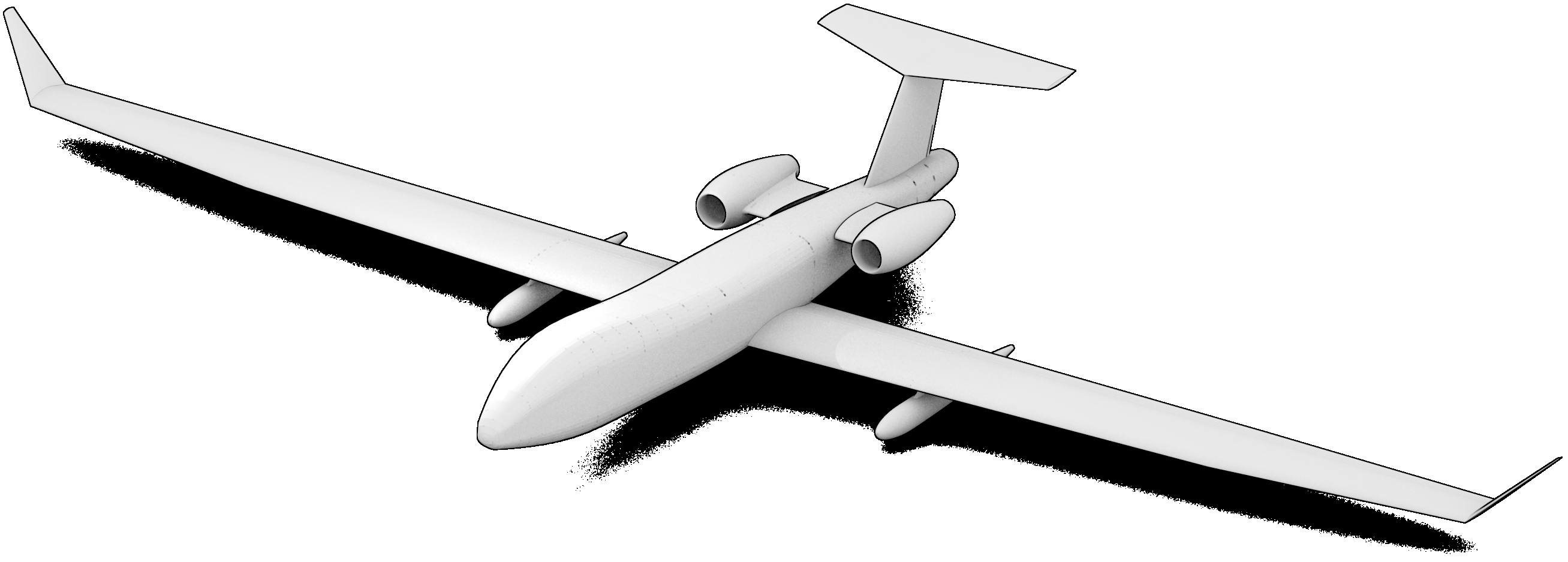
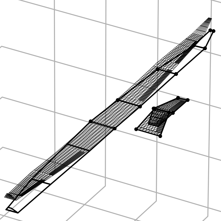
Fig. 3 General arrangement of the OptiMale UAV [AgOp19]
Starting from an undeformed state, a first CFD analysis is performed. The computed loads are shared within the framework. Subsequently, a structure analysis is performed. The previously shared loads are read and mapped onto the structure model. The computed deformations are again shared within framework. The deformation field is now accessible to the CFD analysis, thus the flow field for a deformed aircraft can be analysed. This loop of alternating aerodynamic and structure analyses including the sharing of loads and deformations is continued until the structural deformation has converged. [1] The tasks of interpreting and processing the shared loads and deformations are offloaded to the CFD and structure APIs.
| [1] | To prevent infinite loops due to non-convergent situations, the number of loops can be restricted. |
 ___
___ 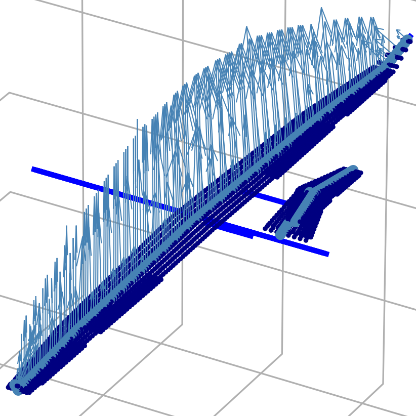
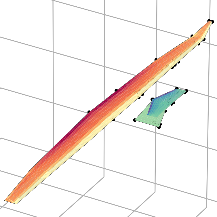
Loads in the 3g pull-up manoeuvre. (a) Qualitative pressure distribution in the undeformed state and (b) nodal loads after projection (nodal moments and inertia loads omitted)
 ___
___ 
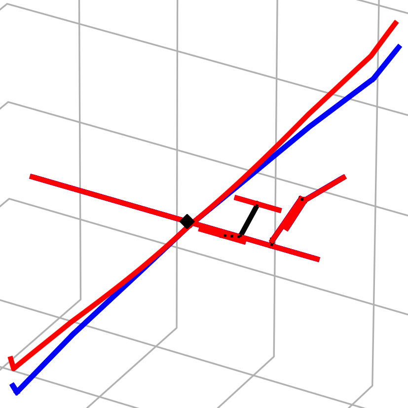
Deformation in the 3g pull-up manoeuvre. (a) Deflection of the FE beam model and (b) deformed VLM mesh
Note
This summary is based on/copied from [Dett19] with the authors permission.
The following pages describe the tool prerequisites, how the wrappers can be set up and how AeroFrame is used.